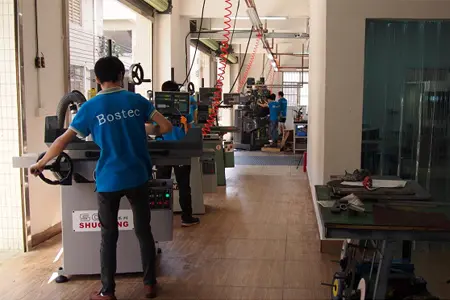
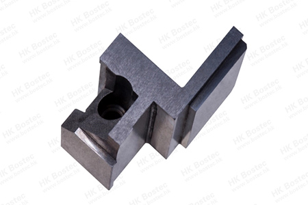
Wire electrical discharge machining is often selected when a component combines hard conductive material, intricate profiles, narrow slots, sharp internal detail, or tolerance relationships that would be difficult to protect with conventional cutting. Yet buyers frequently request “wire EDM” without defining the starting hole, cut length, material condition, taper, surface requirement, inspection method, or quantity. Those omissions can change the process plan and make two quotations difficult to compare.
This guide explains wire EDM from a buyer’s engineering perspective. Instead of treating the process as a generic precision-cutting service, it connects geometry, material, tolerance, surface integrity, speed, and cost. It also compares wire EDM with CNC milling, laser cutting, and precision grinding, then provides a practical RFQ template. Bostec appears throughout the guide as a manufacturing partner that can review drawings and coordinate complementary machining and finishing operations.
Wire EDM machining is a non-contact thermal process that uses controlled electrical discharges between a continuously moving wire electrode and an electrically conductive workpiece to remove material along a programmed path.
The wire and workpiece do not cut through direct mechanical contact. They are separated by a small controlled gap filled with dielectric fluid, commonly deionized water in wire EDM systems. Repeated electrical sparks melt or vaporize microscopic amounts of material, while fluid circulation removes debris and stabilizes the discharge conditions. Because the cutting force is very low, the process can create slender details and machine hardened materials without imposing the same mechanical load as milling or sawing.
Wire EDM can cut through the full thickness of a conductive workpiece, create straight or tapered walls, and follow detailed two-dimensional profiles. Modern machines may coordinate upper and lower wire guides to generate controlled taper or more complex ruled geometry. The process is not appropriate for nonconductive materials unless a specialized conductive layer or another process is used.
Good wire EDM candidates are conductive components whose profile, hardness, thickness, fragility, internal detail, or tolerance makes mechanical cutting difficult, unstable, or uneconomical.
Examples include punch and die components, mold inserts, extrusion tooling, precision slots, keyways, gears, splines, thin flexures, carbide tooling, hardened steel components, medical-device features, electrical contacts, and profile gauges. Wire EDM is also useful for separating precision parts from heat-treated plate when the final profile must be controlled after hardening.
The process is strongest when the cut can be represented by a path through the workpiece thickness. A closed internal contour normally requires a predrilled start hole through which the wire can be threaded. Open profiles can begin from an edge. Blind cavities are not produced by conventional wire EDM; sinker EDM or milling may be more suitable.
Buyers should send section views for parts with different top and bottom profiles. The supplier needs to know whether the wall is straight, tapered, or twisted within the machine’s geometric limits. Small radii are influenced by wire diameter, discharge gap, corner-control strategy, material, thickness, and the number of finishing passes.
Wire EDM tolerance should be specified by identifying the functional profile, datum references, wall condition, corner requirements, thickness, and inspection method rather than applying one tight number to every edge.
A wire path is offset from the final profile to account for the wire radius and spark gap. Machine control, flushing, wire tension, thermal stability, workpiece thickness, material, corner behavior, and cut strategy all influence the result. Rough cutting removes material efficiently, while one or more skim cuts may improve size, straightness, surface finish, and recast-layer condition. More passes can improve quality but add machine time.
Do not assume the same tolerance is equally achievable on a short straight cut, a tall narrow core, a sharp corner, and a large closed contour. Thick workpieces can experience wire lag and flushing challenges. Abrupt direction changes require corner control. Very small internal radii may be limited by wire diameter and the electrical gap. The drawing should identify which dimensions are critical and whether top, middle, and bottom profile measurements are required.
For datum-related profiles, define how the wire-cut contour relates to holes, faces, or features created by other operations. The supplier may machine reference features before EDM, after EDM, or in a coordinated sequence. The process plan should preserve the intended datum relationship.
Wire diameter is one of the factors that influences minimum corner radius, kerf width, feature access, cutting stability, and productivity, but the final capability also depends on spark gap, material, thickness, and machine settings.
A common production wire is around 0.25 mm in diameter, although smaller and larger wires are used for specialized requirements. The smallest theoretical internal radius is not simply half the wire diameter because the discharge gap adds to the effective cutting envelope. Very small wire may create finer features but can reduce cutting speed, require careful handling, and be less robust in thick material.
When a design contains tiny internal corners, ask whether the radius is functional. Increasing it even modestly may allow a more stable wire size or an alternative milling cutter. Conversely, if the corner is required for a mating punch, insert, or flexure function, identify it as critical and request the supplier’s confirmed achievable radius.
Narrow slots also require clarification. State whether the slot width is measured at the top, bottom, or through the full thickness, and whether taper is permitted. For very thin webs between adjacent cuts, the sequence may need to control movement or release stress gradually.
Wire EDM can machine electrically conductive materials regardless of conventional cutting hardness, making it valuable for hardened tool steels, carbides, superalloys, titanium, copper alloys, aluminum, and many specialty metals.
Hardness does not eliminate EDM capability because material removal is electrical and thermal rather than based on a cutting edge shearing the material. However, conductivity, melting behavior, alloy composition, workpiece thickness, residual stress, and flushing conditions affect process stability and speed. Carbide requires particular attention to surface integrity and process parameters. Titanium and nickel alloys may cut more slowly than easier materials.
State the exact grade and heat-treatment condition. “Tool steel” is not enough for a production quote. If the component will be cut after hardening, include the target hardness and whether stress relief has been performed. Wire cutting can release residual stress in plate or heat-treated stock, causing movement after material is removed. A supplier may recommend rough cutting, rest, stress relief, or balanced sequencing before final skim passes.
Bostec’s wire EDM services should be evaluated against the exact material, profile, thickness, tolerance, and certificate requirements shown on the buyer’s drawing.
Wire EDM surface quality is determined by discharge energy, material, flushing, machine settings, and the number of cuts, and it may include a thin thermally affected or recast layer that must be considered for critical applications.
A rough cut prioritizes material removal. Subsequent skim cuts use controlled conditions to refine size, reduce surface roughness, improve straightness, and limit the altered surface layer. The required number of passes depends on the drawing and application. A tool insert that will be polished, a fatigue-sensitive flexure, a sealing profile, and a general clearance part may not require the same cut strategy.
Specify a measurable surface-finish requirement only where it protects function. If a customer specification limits recast layer, microcracking, or surface chemistry, provide the exact acceptance method. Additional polishing, lapping, grinding, or etching may be needed after EDM, but those processes can change size and edge geometry.
For components used in cyclic loading, medical applications, high vacuum, or severe corrosion environments, surface integrity deserves early review. The buyer and supplier should agree whether metallographic evaluation, process qualification, or special cleaning is required.
Wire EDM cost is driven mainly by machine time, cut length, workpiece thickness, material behavior, number of passes, setup, start holes, threading complexity, inspection, and secondary operations.
| Cost Driver | Why It Matters | Buyer Action |
|---|---|---|
| Total cut length | Longer programmed profiles require more machine time | Provide the final geometry and quantity, not only a rough part size |
| Material thickness | Thicker sections can reduce cutting speed and challenge flushing | State finished thickness and stock condition |
| Rough and skim cuts | Additional passes improve size and surface but add time | Limit high finish and tight tolerance to functional areas |
| Internal contours | Each closed profile may need a start hole and threading cycle | Identify start-hole allowance or ask supplier to include drilling |
| Small wire or fine detail | Special wire and slower stable cutting can increase cost | Confirm whether tiny radii and slots are essential |
| Setup and alignment | Datum pickup, fixturing, and workpiece preparation affect labor | Provide accessible datums and a clear inspection plan |
| Inspection records | Full reports and complex profiles require measurement time | Define sampling and documentation in the RFQ |
| Part release and tabs | Loose slugs can move, trap the wire, or damage the workpiece | Allow an approved tab or release sequence where appropriate |
A low-cost quote may include only a rough cut, limited inspection, or assumptions about start holes and material preparation. Ask suppliers to state what is included. For repeat production, nested layout, shared cuts, standardized fixtures, and stable inspection programs may improve economics, but only when they do not compromise traceability or dimensional control.
Wire EDM is usually preferred for conductive through-profiles, hardened materials, narrow features, and low-force cutting, while CNC milling is preferred for pockets, blind cavities, three-dimensional surfaces, nonconductive materials, and faster bulk removal.
| Requirement | Wire EDM | CNC Milling |
|---|---|---|
| Material limitation | Requires electrically conductive workpiece | Works with metals, plastics, and many nonconductive materials |
| Feature type | Through profiles, slots, tapers, fine contours | Pockets, bosses, holes, faces, freeform surfaces |
| Cutting force | Very low mechanical cutting force | Mechanical forces require adequate rigidity and workholding |
| Hardened material | Can cut hardened conductive material effectively | Possible with suitable tools, but hardness affects tool life and strategy |
| Internal corner | Can create small radii governed by wire and spark gap | Radius governed mainly by cutter size and tool access |
| Removal rate | Generally slower for large bulk removal | Efficient for roughing and three-dimensional material removal |
| Surface condition | Thermal process with recast-layer considerations | Mechanically cut surface with tool-mark and burr considerations |
Many parts use both processes. Milling may create reference faces, start holes, pockets, and clamping features before EDM cuts the final profile. After EDM, milling, grinding, or polishing may finish other surfaces. Buyers can review Bostec’s CNC milling services when a project requires a combined process plan.
Wire EDM is typically selected for higher-precision conductive profiles, while laser and waterjet cutting are often selected for faster sheet or plate profiling when their tolerance and edge-condition limits are acceptable.
Laser cutting can be highly productive for sheet metal and may create small features, but heat input, taper, dross, material reflectivity, thickness, and edge condition must be considered. Waterjet cutting can process conductive and nonconductive materials with limited thermal effect, but kerf behavior, taper, edge texture, and precision may differ from finish EDM requirements.
Wire EDM is generally slower, yet it can produce precise profiles in hardened materials and support skim cuts for improved accuracy and finish. The best process may involve rough profiling by waterjet or laser with stock allowance, followed by machining, grinding, or EDM on critical features. This hybrid route can reduce time if the intermediate blank remains stable and leaves sufficient material for final control.
Wire EDM controls conductive profiles through spark erosion, while precision grinding controls surfaces and dimensions through abrasive cutting and is often selected for flatness, parallelism, roundness, size, and fine surface requirements.
A die insert might be wire-cut for its internal profile and then ground on reference faces. A thin plate might be ground to thickness before EDM. A hardened component may need grinding after EDM if the drawing requires a specific surface texture, extremely controlled flatness, or removal of the altered layer.
The sequence matters. Grinding before EDM establishes accurate datums and thickness, but stress released during profile cutting may cause movement. Grinding after EDM can restore flatness or thickness but may affect profile-to-face relationships. The supplier should explain which operation establishes each critical feature.
For integrated work, Bostec’s precision grinding services page provides the correct internal destination for grinding-related requirements rather than overloading the wire EDM page with unrelated keywords.
Start-hole and slug management controls how the wire enters a closed profile, how cut material remains supported, and how the finished part is released without movement or machine interruption.
Each internal contour normally needs a through start hole. The buyer can provide it in the blank or ask the supplier to drill or EDM it. The location must allow the wire to thread while leaving enough material for the final cut. Very small start holes may require hole-drilling EDM or a specialized approach.
When the profile is nearly complete, the internal slug or finished component can become loose. If it shifts, it may pinch the wire, damage the surface, or alter the final segment. Suppliers may leave a small tab, use magnetic or mechanical support, stop for manual removal, or plan a controlled release. The drawing and purchase requirements should state whether a tab witness is permitted and how it must be finished.
For arrays of small parts, the sequence should manage heat, stress, and support. Shared cuts may save time but can change release behavior and traceability. The production plan should ensure that every part remains identifiable through inspection and finishing.
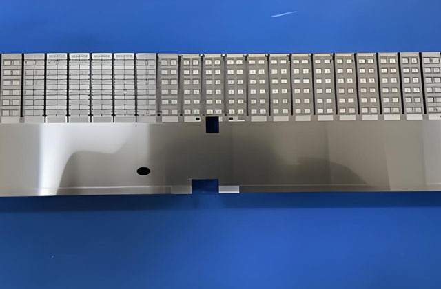
Wire EDM inspection should match the geometry and tolerance, using instruments capable of verifying profile size, taper, straightness, position, surface finish, and relation to the defined datums.
Optical measurement can be useful for detailed profiles and small radii. A CMM can evaluate profile, position, and multi-feature relationships when probe access and uncertainty are suitable. Micrometers, height gauges, gauge blocks, pins, bore gauges, form instruments, and surface-roughness testers may support other requirements. For tall cuts, measurements may be required at different heights to evaluate taper or barrel shape.
Agree on the inspection temperature and part-cleaning condition for very tight work. Thermal expansion, debris, and handling can affect measurements. If the part is flexible or thin, define how it is supported during inspection. A free-state requirement differs from a restrained measurement.
For complex profiles, provide a digital inspection definition or a ballooned drawing so both parties measure the same characteristics. If a custom gauge is required, state who owns it, how it is calibrated, and whether it will be retained for repeat orders.
Typical wire EDM risks include wire breakage, unstable discharge, poor flushing, taper error, corner error, recast-layer concerns, released-stress distortion, slug movement, and incorrect datum transfer.
Wire breakage: may result from aggressive settings, poor flushing, contamination, difficult geometry, or unstable conditions. A robust program balances speed with reliability.
Corner error: abrupt direction changes can cause wire lag and overcut or undercut behavior. Machine corner-control functions and finishing passes help manage the result.
Taper or straightness variation: can be influenced by thickness, guide alignment, flushing, wire tension, and cut conditions.
Distortion: removing material can release residual stress. Rough-and-rest strategies or stress relief may be required.
Surface integrity: discharge energy and pass count affect the altered surface layer. Critical applications may need qualified settings or secondary finishing.
Datum mismatch: if reference features are created in another setup, the process must control their relationship to the EDM profile.
A capable supplier should discuss these risks during DFM rather than wait for final inspection to reveal them.
A complete wire EDM RFQ defines the controlled geometry, material, thickness, profile requirements, start-hole responsibility, surface condition, inspection records, quantity, and delivery expectations.
Send a STEP model and dimensioned PDF drawing with revision control.
Identify the exact conductive material, condition, hardness, and certificate needs.
State workpiece thickness and whether it is finished before EDM.
Mark critical profiles, corner radii, slot widths, taper, and datum relationships.
Define whether the cut requires roughing only or a specified finish and tolerance.
Identify internal contours and who will provide start holes.
State whether tabs or witness marks are permitted and how they should be removed.
Define surface-integrity, cleaning, burr, and edge requirements.
Specify inspection report, sampling, and measurement method where controlled.
Provide prototype quantity, production quantity, annual forecast, and delivery location.
Ask suppliers to list assumptions and outside processes. If the quote includes a combined route, request a simple operation sequence showing where milling, heat treatment, EDM, grinding, finishing, and inspection occur.
These frequently asked questions clarify the limits, economics, and sourcing requirements most buyers encounter when evaluating wire EDM.
Conventional wire EDM requires an electrically conductive workpiece. Nonconductive materials normally require another process, although specialized approaches may use conductive coatings for limited applications.
Hardness does not create the same cutting resistance as it does in milling, but material composition, conductivity, thickness, residual stress, and surface-integrity requirements still affect process settings and results.
Skim cuts refine size, straightness, corner behavior, surface finish, and surface integrity. The appropriate number depends on the tolerance, material, thickness, and application.
No physical cutting process creates a mathematically zero-radius internal corner. The achievable radius is influenced by wire diameter, spark gap, machine control, and material conditions.
Total cut length, thickness, material, number of contours, start holes, pass count, small-feature requirements, setup, inspection, and quantity are major cost factors.
Many tooling parts are heat treated before final wire cutting so the finished profile is created in the hardened condition. The correct sequence depends on distortion risk, material, tolerance, and downstream finishing.
The following sources provide additional background and standards context. They are listed separately so that the main article remains focused on the buyer’s decision process.
Wire EDM is most valuable when its low cutting force, hardened-material capability, and precise profile control solve a real geometric or quality problem. The buyer’s responsibility is to define the profile, datums, material condition, thickness, corner requirements, surface integrity, inspection, and part-release rules clearly. The supplier’s responsibility is to select a stable cut strategy, explain cost assumptions, manage start holes and slugs, and coordinate complementary machining or grinding operations.
Bostec can review conductive precision parts and propose a process route based on the actual drawing, quantity, material, and quality requirements. Sending a controlled model and drawing package is the best way to receive a technically meaningful wire EDM quotation.