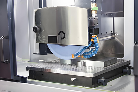
A successful five-axis machining project starts long before the first tool touches the workpiece. It begins with a drawing package that explains which surfaces control function, which tolerances are truly critical, how the component will be inspected, and what quantity the buyer expects over the life of the program. When those details are clear, a machining supplier can select the right machine strategy, workholding method, tool access, inspection sequence, and production route. When they are missing, even advanced equipment cannot prevent unnecessary quoting assumptions, setup risk, or schedule changes.
This guide is written for engineers, sourcing teams, product developers, and quality professionals who need complex machined parts but do not want to treat five-axis machining as a black box. It explains how to prepare a request for quotation, distinguish simultaneous five-axis cutting from indexed machining, evaluate part geometry, control tolerance risk, and compare supplier proposals. It also shows where Bostec can support design review, prototype machining, and production planning for metal and engineering-plastic components.
A five-axis CNC project specification is the complete set of technical and commercial information a supplier needs to select a machining strategy, estimate risk, verify inspectability, and quote a repeatable process for a complex component.
The package should include a controlled 3D model, a dimensioned 2D drawing, material and condition, surface-treatment requirements, target quantity, inspection expectations, and delivery priorities. The model defines the nominal geometry, while the drawing identifies functional requirements that cannot be inferred safely from geometry alone. These may include datums, geometric tolerances, surface-finish limits, edge conditions, thread standards, cosmetic zones, and critical-to-function dimensions.
The phrase “five-axis” describes a machine’s ability to control motion along three linear axes and two rotary axes. It does not automatically mean that all five axes move continuously during every cut. Some components are best produced by indexed or 3+2 machining, where the part is rotated into a new orientation and then cut with three linear axes. Other shapes require simultaneous five-axis tool motion to maintain access, orientation, or surface continuity. The correct method depends on geometry, tolerance, finish, collision risk, and production economics.
For buyers, the practical objective is not to request the most complex process. It is to define the part accurately enough that the supplier can choose the simplest robust process that meets the drawing.
Five-axis machining is used when a component contains features on multiple faces, deep or angled geometry, compound surfaces, difficult tool-access directions, or positional relationships that become harder to control through repeated re-clamping.
A conventional three-axis machine can produce many sophisticated parts, but each inaccessible face may require a new fixture orientation. Every additional setup introduces decisions about locating, clamping, datum transfer, and re-verification. Five-axis positioning can expose several faces in one controlled setup, which may reduce fixture complexity and protect relationships between features. The benefit is especially important when a hole, pocket, sealing face, and angled interface must remain aligned to the same datum system.
However, “one setup” should not be treated as a guaranteed rule. Parts may still require a second operation to remove the holding stock, machine the clamped face, or complete features that are inaccessible in the first orientation. A reliable supplier will explain the planned setup count and identify which datums are established in each operation.
Five-axis machining is commonly considered for aerospace brackets, optical mounts, semiconductor equipment components, medical-device hardware, automation fixtures, robotic end-effectors, fluid manifolds, turbine-related geometry, and precision mold inserts. The same process can also be useful for lower-complexity parts when a consolidated setup improves repeatability or shortens the production route.
A functional datum structure defines how a component is located in its real assembly and provides the reference system for manufacturing and inspection.
Before sending an RFQ, identify which face, bore, axis, or pattern establishes the part in service. The drawing should use a datum reference frame that reflects that function rather than choosing convenient surfaces arbitrarily. A primary datum typically stabilizes the part, a secondary datum controls rotation or translation, and a tertiary datum completes the location. The exact scheme depends on geometry and assembly behavior.
This information affects workholding. If a thin sealing face is the primary datum but cannot be clamped without distortion, the supplier may need sacrificial stock, soft jaws, a vacuum fixture, adhesive workholding, or an intermediate reference feature. If the drawing uses a hidden or difficult-to-measure surface as a datum, inspection cost and uncertainty may rise. Early review lets the buyer and supplier preserve design intent while making the datum system practical.
Do not use every dimension as a tight coordinate tolerance. Where appropriate, geometric dimensioning and tolerancing can communicate position, profile, perpendicularity, runout, flatness, or parallelism more clearly. The supplier should be able to explain how the chosen machining and inspection process will verify those controls.
3+2 machining locks the rotary axes at a selected orientation before cutting, while simultaneous five-axis machining moves linear and rotary axes together during the cutting path.
| Decision Factor | 3+2 Indexed Machining | Simultaneous Five-Axis Machining |
|---|---|---|
| Typical geometry | Multiple planar faces, angled holes, pockets, and features that can be reached from fixed orientations | Compound surfaces, continuously changing tool angles, undercut access, impellers, sculpted transitions |
| Programming complexity | Generally lower because each cutting orientation behaves like a three-axis operation | Higher because tool orientation, collision control, machine kinematics, and surface continuity interact |
| Tool length | Can often use shorter tools by tilting the part toward the spindle | Can maintain a favorable tool angle continuously and avoid excessive reach |
| Surface behavior | Good for distinct faces; blend zones may require careful planning | Useful for continuous freeform surfaces when smooth tool orientation is important |
| Cost sensitivity | Often more economical when fixed orientations meet the drawing | Justified when geometry or finish cannot be achieved reliably with indexing alone |
Buyers do not need to prescribe the method unless the process itself is controlled by a customer specification. Instead, describe the functional geometry and let the supplier propose the route. If two suppliers choose different approaches, ask each one to explain setup count, tool access, inspection strategy, and the risks their method is designed to avoid.
Bostec’s 5 axis CNC machining services page is the appropriate internal reference for projects that require multi-face access or complex tool orientation. A quotation should still be based on a review of the final model, drawing, material, quantity, and inspection requirements.
A 3D model communicates nominal geometry efficiently, while a controlled 2D drawing communicates tolerances, datums, finishes, notes, acceptance criteria, and revision authority.
STEP is widely used for neutral solid-model exchange, while native CAD files may help when design history or product manufacturing information is relevant. The supplier should confirm which formats it can read reliably. The drawing should include a part number, revision, units, material specification, heat-treatment condition, general tolerances, critical dimensions, threads, surface finish, edge-break requirements, and any prohibited changes.
Resolve model-versus-drawing conflicts before production. A useful purchase note states which document controls if a discrepancy appears. Avoid sending several files with similar names and no revision status. Use a single package with a transmittal list so that the supplier, buyer, and inspector are working from the same release.
For complex surfaces, identify whether the 3D model is basic and controlled by a profile tolerance or whether specific drawing dimensions control selected features. If a surface is cosmetic, define the visible zone and acceptance standard. If a surface is functional, state the mating condition, sealing requirement, flow function, optical role, or assembly relationship that makes it important.
Material specification must define not only the alloy or polymer family but also the grade, condition, temper, heat treatment, stock form, and traceability level required for the application.
For aluminum, the difference between common tempers can affect strength, residual stress, distortion, anodizing appearance, and cutting behavior. For stainless steels, condition and sulfur content can influence machinability and corrosion performance. For titanium, tool access, heat management, and workholding rigidity become central concerns. Engineering plastics require attention to moisture absorption, internal stress, thermal expansion, and stock conditioning.
Specify whether substitutions are prohibited or may be approved in writing. If material certificates are required, state the certificate type and whether lot traceability must continue through machining and finishing. When a component will be heat treated or anodized after machining, define whether final dimensions apply before or after the secondary process.
The broader CNC machining services capability page can help buyers review the relationship between machining route, material, and part geometry. For any safety-critical or regulated component, the purchase order and approved drawing should remain the final authority.
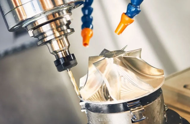
A tolerance is useful only when it protects function, can be produced repeatably, and can be verified with an appropriate measurement method.
Bostec’s published FAQ states that precision machining tolerances as tight as ±0.005 mm may be achievable, but that number should never be copied across an entire drawing. Actual capability depends on feature size, geometry, material, thermal stability, tool access, setup, measurement method, and quantity. A tiny bore, a large plate, a deep pocket, and an angled freeform surface do not share the same process capability.
Classify dimensions into functional tiers. Critical dimensions directly affect sealing, alignment, bearing fit, optical position, motion, or interchangeability. Important dimensions affect assembly or performance but have more process latitude. Noncritical dimensions can follow a sensible general tolerance. This hierarchy helps the supplier focus process control and inspection resources where they create value.
Also define whether the tolerance is bilateral, unilateral, limit-based, or geometric. A position tolerance on a hole pattern may communicate assembly intent better than separate ± coordinate tolerances. Profile can control an irregular surface relative to datums. Runout may be appropriate for rotating features. The drawing should reflect the real acceptance condition rather than the easiest notation.
Thin walls, deep cavities, long-reach features, small internal radii, and interrupted cuts increase the risk of deflection, chatter, heat, tool wear, and dimensional movement.
For thin walls, explain which surfaces are functional and whether slight cosmetic witness marks are acceptable. The supplier may sequence roughing and finishing to balance stress, leave support stock temporarily, use low-force finishing passes, or design custom workholding. For deep pockets, the ratio between depth, opening, corner radius, and tool diameter affects access and stability. Increasing an internal corner radius can allow a larger, stiffer tool and reduce machining time.
For angled holes and intersecting passages, provide section views or model-based definition so the supplier can identify breakthrough conditions and burr locations. State whether internal burrs are permitted, must be removed, or must meet a specific inspection requirement. For freeform surfaces, identify blend zones and areas where cutter marks would affect function.
A useful DFM review should show the buyer which changes reduce risk without altering function. The supplier should not silently modify geometry. Every proposed change should be documented and approved through the drawing revision or deviation process.
Workholding is the method used to locate, support, and restrain a workpiece while protecting access, rigidity, and datum repeatability.
Complex parts often need tabs, bosses, extra stock, clamping pads, dovetails, threaded fixture holes, or a sacrificial base. These features may not appear on the finished component, but they can make the process more stable. Ask the supplier whether the raw blank needs additional material and whether fixture features will be removed in a later operation.
Workholding also affects cosmetic requirements. A visible surface may show jaw marks, vacuum patterns, adhesive residue, or handling evidence unless it is protected. Mark cosmetic zones on the drawing and define whether minor marks are acceptable outside them. If a part will be anodized or polished, discuss how fixture contact points and masking will be handled.
For low quantities, modular fixtures or machined soft jaws may be appropriate. For repeat production, dedicated fixtures can improve loading consistency and inspection correlation. The economic decision should consider expected lifetime volume, repeat orders, design stability, and the cost of re-qualification.
Surface requirements should distinguish functional roughness, cosmetic appearance, edge condition, and secondary treatments because each one affects the machining route differently.
Do not apply one roughness value to every surface unless every surface truly needs it. A sealing land, bearing seat, sliding interface, optical mount, and hidden clearance face have different needs. Identify machined-as-finished areas and surfaces that will later be ground, polished, coated, anodized, painted, or heat treated.
Edge notes should define whether the part requires a general deburr, a measurable edge break, a chamfer, or a controlled radius. “Break all sharp edges” is common but can be ambiguous on miniature features or precision intersections. State which edges must remain sharp for sealing or alignment and which ones need safe handling.
Secondary operations can change dimensions. Anodizing builds and penetrates the aluminum surface; heat treatment can cause distortion; coating adds thickness; polishing can remove material and soften edges. The supplier needs to know the final process sequence and whether the drawing dimensions apply at the finished condition.
An inspection plan defines what will be measured, when it will be measured, which instrument or method will be used, and what records must accompany the shipment.
For five-axis parts, not every feature is easy to inspect with conventional gauges. A coordinate measuring machine may be appropriate for datum-related position, profile, and multi-face geometry. Surface plates, height gauges, bore gauges, micrometers, optical systems, contour instruments, and roughness testers may be used for other characteristics. The method must be suitable for the tolerance and feature accessibility.
Ask whether the quote includes a standard inspection report, full dimensional report, first article inspection, material certificate, process certificate, or CMM report. If a regulated format is required, state it in the RFQ. Also define sampling: first piece, first and last piece, a percentage of the lot, or 100% inspection for selected characteristics.
Measurement uncertainty matters when a tolerance is very tight. A result near the limit may not be meaningful if the measurement system cannot resolve the requirement reliably. The supplier should be willing to discuss the measurement method rather than simply state that the feature will be “checked.”
A technically complete quote explains assumptions, exclusions, setup strategy, inspection scope, secondary processes, lead time, and change-control conditions in addition to unit price.
| Quote Element | What a Buyer Should Look For | Risk if Missing |
|---|---|---|
| Revision and file list | Exact drawing and model revision referenced | Parts may be produced from an outdated file |
| Material and condition | Grade, temper or condition, certificate requirement | Performance or finishing variation |
| Manufacturing route | Planned setups, major operations, outside processes | Hidden assumptions and schedule changes |
| Inspection scope | Included records, sampling, special reports | Unexpected quality-document cost |
| Tooling and fixture charges | One-time versus recurring charges explained | Misleading unit-price comparison |
| Lead-time definition | Starts after drawing approval, material receipt, or deposit | Different suppliers may quote different starting points |
| Nonconformance process | Communication, containment, and corrective-action approach | Slow resolution if a problem occurs |
The lowest quote may be based on broader assumptions, limited inspection, an easier material condition, or a different interpretation of cosmetic requirements. Ask clarifying questions before award. A supplier acting as a precision machining company should be able to describe how its proposal protects critical features and how engineering changes will be controlled.
A staged release separates learning, validation, and production so that design or process risks are resolved before a larger quantity is committed.
A practical sequence may include a DFM review, one or a few prototype pieces, dimensional and functional evaluation, a corrected pilot batch, and then routine production. The exact stages depend on cost, urgency, risk, and regulatory requirements. For a stable repeat part, the buyer may also request retention of fixture data, tool lists, inspection programs, approved samples, and controlled process notes.
During prototype review, document every approved deviation or interpretation. Do not rely on email memory alone. Update the drawing or create an approved deviation record so that the production release is unambiguous. If the prototype is accepted despite a nonconforming dimension, state whether that acceptance applies only to the prototype or changes the ongoing requirement.
For repeat orders, confirm whether the material source, outside-processing route, inspection method, and critical tooling remain the same. Process changes may be beneficial, but they should be reviewed when they can affect fit, finish, traceability, or validation status.
Five-axis RFQs are delayed most often by uncontrolled revisions, undefined critical features, incomplete secondary-process requirements, unrealistic blanket tolerances, and missing inspection expectations.
Sending only an STL file: a tessellated mesh may not provide the controlled surfaces and manufacturing definition needed for a precision quote.
Using a single general tolerance for the whole part: this can make noncritical surfaces unnecessarily expensive while leaving functional relationships unclear.
Omitting material condition: the same alloy designation may be available in conditions with different stability and performance.
Adding finishing after the quote: anodizing, coating, polishing, or heat treatment can change dimensions, masking, lead time, and handling.
Not identifying cosmetic faces: suppliers cannot protect appearance zones they do not know exist.
Requesting a tight profile without a datum system: the requirement may be difficult to interpret or inspect.
Comparing lead times with different assumptions: one quote may begin after material receipt while another begins after drawing approval.
A complete RFQ does not need to prescribe every cutter and toolpath. It needs to communicate design intent, acceptance criteria, and commercial constraints clearly enough for the supplier to engineer the process.
A five-axis RFQ checklist is a final verification tool that confirms the supplier has the geometry, quality, finishing, quantity, and delivery information needed to quote without avoidable assumptions.
Controlled part number and revision
STEP or another agreed solid-model format
Dimensioned PDF drawing with datum structure
Material grade, condition, stock preference, and certificate needs
Critical tolerances and functional notes
Surface-finish requirements by surface
Threads, inserts, edge breaks, and burr requirements
Heat treatment, anodizing, coating, polishing, or other secondary processes
Cosmetic zones and appearance standard
Prototype, pilot, annual, and order quantity
Inspection report and sampling expectations
Required delivery date and shipping destination
Packaging, cleanliness, and part-marking requirements
Confidentiality or export-control requirements where applicable
Contact person for engineering questions and deviation approval
Providing these items early helps Bostec review manufacturability and prepare a quote that is easier to compare. Final capability and price should always be confirmed against the actual drawing and project conditions.
These frequently asked questions address the most common engineering and sourcing decisions that arise before a five-axis machining order is placed.
No. Many multi-face components can be produced efficiently with 3+2 indexed machining. Simultaneous motion is normally selected when the surface or access condition requires continuous tool-orientation changes.
A preliminary estimate may be possible, but a controlled drawing is strongly recommended for a production quote because it defines tolerances, datums, finish, threads, inspection, and revision status.
Bostec publishes a general precision capability as tight as ±0.005 mm in its FAQ. The achievable tolerance for a specific five-axis feature depends on size, geometry, material, setup, thermal conditions, tool access, and measurement method, so the drawing must be reviewed.
Common options include relaxing noncritical tolerances, increasing internal corner radii, reducing extreme pocket depth, allowing practical workholding features, separating cosmetic and functional finish requirements, and consolidating revisions before release.
Choose documents according to project risk. Options may include a standard dimensional report, full inspection report, CMM report, first article inspection, material certificate, and secondary-process certificate.
Yes. Five-axis machining can be valuable for prototypes and low-volume parts when it reduces dedicated fixtures, improves multi-face alignment, or gives access to geometry that would otherwise require several setups.
The following sources provide additional background and standards context. They are listed separately so that the main article remains focused on the buyer’s decision process.
A well-prepared five-axis CNC project is defined by engineering clarity rather than by the machine name alone. The buyer should establish functional datums, provide a controlled model and drawing, define material condition, prioritize tolerances, identify finishing and cosmetic requirements, and agree on an inspection plan before production. The supplier should respond with a transparent setup strategy, manufacturability feedback, documented assumptions, and a staged path from prototype to repeat production.
Bostec can review complex component requirements and recommend an appropriate machining route based on geometry, material, quantity, quality documentation, and delivery needs. The most productive next step is to submit the current drawing package and ask for a DFM and tolerance review before finalizing the order.